In the realm of precision engineering, where every fraction of an inch matters, two vital concepts hold sway: straightness and flatness. These seemingly simple terms, often used interchangeably, lie at the very heart of achieving meticulous accuracy. Yet, beneath their shared pursuit of perfection, lies a fundamental distinction that can make all the difference in the world. Join us on a captivating journey as we unravel the mystique surrounding straightness and flatness, and delve into the nuanced contrasts that shape their unique identities. Prepare to embark on a quest for clarity, where we navigate the fascinating realms of geometric precision and discover how these unassuming dimensions wield extraordinary power in the world of engineering and beyond.
In Geometric Dimensioning and Tolerancing (GD&T), straightness and flatness are two distinct concepts that are used to define the shape and form of a feature on a part. While they may seem similar, they have different applications and interpretations. Here’s an explanation of the difference between straightness and flatness in GD&T:
Straightness in GD&T
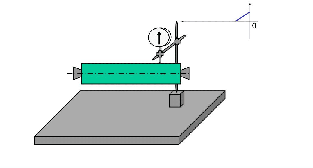
Straightness is a GD&T characteristic that defines the form of a line or feature. It ensures that an element remains within a specified tolerance zone, which is essentially a cylinder or a tube around the ideal line or feature. The straightness tolerance zone is defined by two parallel planes that are equidistant from the ideal line. Any deviation of the line within this tolerance zone is considered acceptable.

Straightness is applicable to features such as edges, axes, and centerlines of cylinders or cones. It is commonly used when ensuring proper alignment, controlling the fit of mating parts, or guaranteeing the linear motion of mechanical components. The straightness tolerance value is expressed in units of length, such as millimeters or inches, and indicates the maximum allowable deviation from the ideal line.
Flatness in GD&T
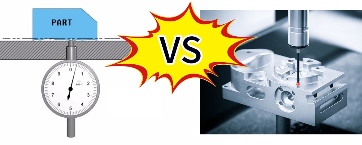
Flatness, on the other hand, is a GD&T characteristic that governs the form of a surface. It defines the allowable variation in the shape of a surface, ensuring that it remains within a specified tolerance zone. The flatness tolerance zone is defined by two parallel planes that are equidistant from the ideal surface. Any deviation of the surface within this tolerance zone is considered acceptable.

Flatness is typically used to control the planar characteristics of surfaces, such as the top or bottom surfaces of a part. It ensures that a surface is free from warping, twisting, or other forms of distortion that could affect the functionality or assembly of the part. The flatness tolerance value is expressed in units of length, such as millimeters or inches, and indicates the maximum allowable variation in the surface’s shape.
Differences Between Straightness and Flatness
While both straightness and flatness deal with deviations from an ideal form, there are key distinctions between them:
1. Dimensional Focus: Straightness focuses on controlling the form of a line or feature, while flatness focuses on the form of a surface.
2. Tolerance Zone Shape: Straightness defines a cylindrical tolerance zone around the ideal line, while flatness defines a parallel planar tolerance zone around the ideal surface.
3. Geometric Application: Straightness is commonly used for aligning features or controlling linear motion, whereas flatness is employed to ensure planarity or proper contact between surfaces.
4. Feature Types: Straightness is applicable to lines, edges, axes, and centerlines, while flatness is applicable to planar surfaces.
In GD&T, straightness and flatness are two distinct characteristics used to control the form of lines/edges and surfaces, respectively. Straightness ensures that a line or feature remains within a specified tolerance zone, while flatness guarantees the planar shape of a surface. Understanding the difference between these two GD&T symbols is crucial for accurate communication of design and manufacturing requirements. By applying the appropriate straightness or flatness tolerance, engineers and manufacturers can achieve the desired functionality, fit, and assembly of parts, thereby enhancing overall product quality.