Gears, along with screws and springs, are parts used in many products. There is a wide variety of sizes, shapes, and materials depending on the application. In addition, there are various functions, and it can be used for various purposes by combining gears and gears, as well as shafts and cams. And all gears are made with high precision.
However, with increased use, for example, deformation due to wear occurs. Among them, the dimension of “tooth thickness” is important, and it greatly affects not only the operation of the gear but also the strength.

Here, the concept of basics and strength, such as the names of each part of the gear. In addition, we will explain how to measure tooth thickness. We would also like to touch on how to solve the difficult, inaccurate and laborious measurement of tooth thickness.
What Is Gear Tooth Thickness?
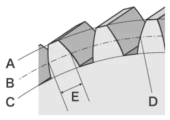
“Tooth thickness” is the thickness of one tooth on the pitch circle. Gears come in a variety of shapes, but here we will take the most common spur gears as an example. The spur gear has the structure shown in the figure.

A – Tooth tip circle / B – pitch circle / C – Fundus circle / D – Pitch point / E – Tooth thickness
Causes of Gear Tooth Thickness Changes
During rotation, bending loads (bending moments), contact pressures, compressive loads, etc. are applied to the teeth of the gear. Also, if the tooth and other parts mesh, friction will occur in the tooth and wear out. When the tooth is deformed or worn and the tooth thickness changes, the backlash increases and various troubles such as noise and vibration occur. When using gears, these loads and wear must be carefully considered. The strength of a gear is determined by the “bending load (bending moment)” when the hardness (hardness) is high and the possibility of damage due to pitching is low, and the “tooth surface strength” when the hardness is low or the gear is operated for a long time.
Change In Gear Thickness Due To Bending Load (Bending Moment)
A large load is applied to the teeth of a gear, which is called a “bending load”. Bending load is the load on a single tooth. When the bending load exceeds the tooth surface strength of the gear tooth, the tooth is deformed.
The load on the teeth of a gear can be considered in terms of the “beam theory” of the mechanics of materials. Cantilevered beams generate stress concentrations at the base of the beams and are subjected to large loads. In the case of gears, the teeth are also considered as cantilever beams, and the load applied to the base of the gear is the bending load.
Gear Tooth Thickness Formula
The bending load can be determined by the following equation:
M=F・l=σ・Z
M: Flexural Load / F: Load / l: Overall Tooth Length / σ:Maximum Flexural Stress / Z: Cross-sectional Factor
The “cross-sectional coefficient” is the value obtained by dividing the area of the tooth by “6”, and the “maximum bending stress” is the value obtained by dividing the bending load by the cross-sectional coefficient. Gears have complex shapes, and accurate strength calculations are not easy. Variations in load depending on the operating conditions must also be taken into account.
What Is Gear Tooth Surface Strength?
“Tooth surface strength” refers to the limit of the pressure that the tooth surface can withstand. The gears come into contact at the pitch point and transmit rotational force. When the gears come into contact with each other, the teeth are repeatedly subjected to a large force, causing wear and scratches on the tooth surface. In addition, small cracks can cause breakage called “pitching”.
In order to prevent such troubles, the strength is calculated based on the stress when the contact surface is deformed, called the maximum contact stress* of Hertz, and the tooth surface strength of the gear to be used is determined in advance.
* The maximum stress applied to the elastic contact between two objects, such as a spherical surface and a spherical surface, a cylindrical surface and a cylindrical surface, or a spherical surface and a flat surface.
Changes In Gear Tooth Thickness Due To Wear
Greater friction between the gear teeth and other meshing parts causes wear, resulting in a smaller tooth thickness and greater backlash. As further wear progresses, the lubricant becomes more fouled, resulting in greater noise and vibration, and an increase in gear temperature. The causes of such wear include:
- Insufficient gear strength (tooth surface strength)
- Poor assembly
- Deformation of gears, shafts, etc.
- Defective lubricant
- and so on.
In addition, gear wear is called differently depending on the condition as follows:
- Polishing: A state in which minute irregularities on the tooth surface have been removed and it has become smooth like a mirror surface.
- Abrasive wear: Linear grooves run irregularly in the direction of sliding of the tooth surface, resulting in scratches.
- Scratching: A type of abrasive wear. A linear groove runs through it, and the tooth surface becomes like it has been dug up with a plow.
- Scoring: Alternating welding and tearing of the tooth surface and deterioration of the tooth surface.
Conventional Measuring Methods Of Gear Tooth Thickness
Conventionally, the “chord tooth thickness method”, “straddle tooth thickness method”, “overpin method” using hand tools, contour shape measuring machines and gear measuring machines have been used to measure tooth thickness. However, even the easiest spur gears to measure took a knack and time to measure. In addition, gears with complex shapes, such as helical and bevel gears, were sometimes difficult to measure.
Challenges Of Measuring Gear Tooth Thickness Using With Hand Tools
There are two methods for measuring tooth thickness using hand tools: the “straddling tooth thickness method” and the “overpin (ball) method”.
Straddling tooth thickness method
It is used as the most common method of measuring tooth thickness. It is a measurement method in which a certain number of teeth are sandwiched between a measuring device such as a tooth thickness micrometer, their length is measured, and the thickness of the teeth is measured from the number of teeth. The measured value may differ depending on how well the measuring device hits. It is also affected by pitch and tooth profile, so it is laborious to measure the entire circumference of the gear several times.
Overpin method
It is a tooth thickness measurement method also called the “ball method”. In addition to external gears, it is also possible to measure the tooth thickness of internal gears. In the case of even-numbered teeth, a pin or ball is placed in the opposite groove, and in the case of odd-numbered teeth, a pin or ball is placed in the groove that is biased by 180/z (°). The outer dimension (over-pin dimension) of the external gear and the inner dimension (bituin pin diameter) of the internal gear are measured to determine the tooth thickness.
Challenges Of Measuring Gear Thickness Using Contour Measuring Machines
A contour measuring machine is a device that measures and records the contour shape of an object by tracing the surface of an object using a stylus called a stylus. In recent years, there have been models that use lasers instead of stylus to trace contours without contact to measure complex shapes. In addition, some models can measure both the upper and lower sides.
In contour profilometers, it is necessary to take an accurate measuring line for the gear teeth.
Therefore, there were the following issues:
- It takes time to fix the sample to the jig and level it. In addition, knowledge and skills related to contour measuring machines are essential for accurate leveling.
- The stylus of the contour profilometer moves arcs up and down around the fulcrum on the stylus arm, and the position of the stylus tip also moves in the X direction, so errors also occur in the X-axis data.
- It is very difficult to pass the needle as intended, and subtle needle misalignment can cause variations in measured values.
- Since it is necessary to aim and measure at a specific point, it is difficult to increase N.
- Since only a part of the measurement can be taken, it is not possible to evaluate it in terms of aspects.
Problem Solving Method In Gear Tooth Thickness Measurement – 3D Scanning
General measuring machines that have been used for a long time have problems such as it takes time to fix the object and that it is measured while contacting a three-dimensional object or measurement point with a point or line. In order to solve these measurement problems, one-shot 3D scanning measuring machines are created.
With the 3D Scanning machine, it is possible to quickly measure and quantify gear thicknesses that could not be measured due to the limited number of N due to the time required to measure in the past, or because of their complicated shape. This makes it possible to evaluate gear quality at a higher level more efficiently.
- Since it measures by surface, it is easy to measure a large area. It is possible to measure not only the shape of the tooth surface, but also various parameters such as roughness.
- It eliminates variations in measured values by humans and realizes quantitative measurements.
- Without positioning, simple operation is realized by simply placing an object on the stage and pressing a button. Eliminate individualization of measurement work.
- Since 3D shapes can be measured easily, at high speed, and with high accuracy, it is possible to measure many objects in a short time, which can be useful for quality improvement.
In addition, since it is possible to easily analyze comparison with past 3D shape data and roughness distribution, it can be used for various purposes such as trend analysis of fracture surface state due to temperature and confirmation of fracture state.