Parts have design intentions such as “I want this part to be a flat surface within a certain range of conditions” or “I want it to be straight” for the convenience of establishing a function or assembling it. When displaying a shape in a drawing, it is necessary to ensure that such information is included, and the rule is that it is displayed in the form of geometric tolerances in the drawing. In this article, we’ll cover the basics of geometric tolerances that designers and producers need to understand, the types of geometric tolerances that are commonly used, and how to fill them out.
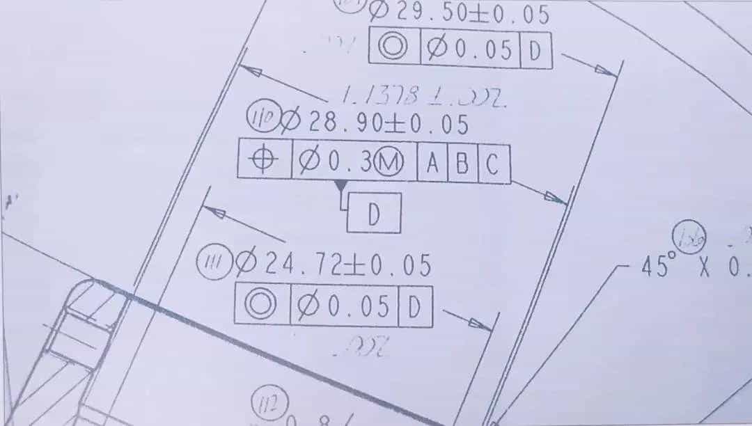
Basic Knowledge Of Geometric Tolerances
When a part is mass-produced, there is always variation. Tolerance is an indication of how much variation is acceptable, and there are two types of tolerances: dimensional tolerance and geometric tolerance. I will briefly explain each of them.
What Is Geometric Tolerance?
Parts and products have dimensions and geometric properties. Geometric tolerance refers to the range of error in the geometric properties allowed for each part and is one of the information included in the drawing to correctly communicate the design intent. The geometric tolerance is (GD&T:Geometric. Dimensioning and Tolerancing).
Difference From Dimensional Tolerance (Size Tolerance)
Dimensional tolerance refers to the margin of error of how much the size of a part or product can tolerate. In general, in a design drawing, tolerances are specified in addition to the design dimensions. If dimensions alone do not adequately explain the design intent of a part, geometric tolerances may also be indicated.
Main Types Of Geometric Tolerances
Geometric tolerances can be classified into shape tolerances, attitude tolerances, position tolerances, and sway tolerances according to their meaning. Also, depending on the type of geometric tolerance, it may be necessary to specify the datum to indicate where the reference is.
(1) Single Form
It is a tolerance that can be specified for the shape itself. When defining geometric tolerances, it is common to first specify geometric tolerances for a single shape as a datum.
- Straightness
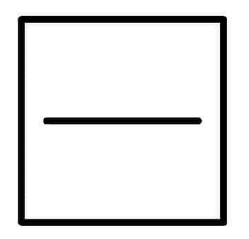
It indicates how straight it is relative to the shape (axis) of a straight line. A tolerance that indicates how many openings from a geometrically correct straight line is acceptable. (Datum: Not required)
- Flatness
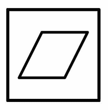
The tolerance for opening from the geometrically correct plane on the same plane. Indicates within the error range of the lowest and highest positions. (Datum: Not required)
- Roundness
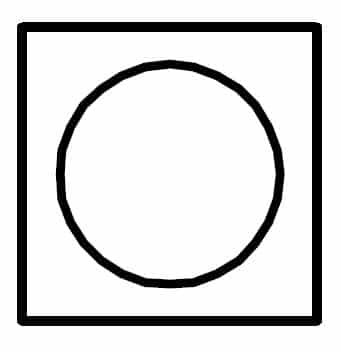
The roundness tolerance of opening from a geometrically correct circle. Indicates the error range of the circle size. ( Datum: Not required)
- Cylindricity
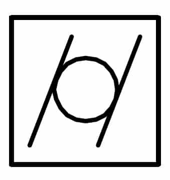
The tolerance for opening from a geometrically correct cylinder. Indicated within the error range of the circle size at both ends of the cylinder. ( Datum: Not required)
- Profile of a line
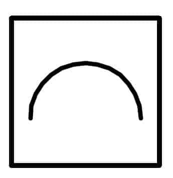
The tolerance of a line from a geometrically correct contour laid down by theoretically accurate dimensions. Indicates the specified shape within the error range. ( Datum: Not required)
- Profile of a surface
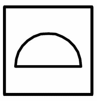
The tolerance of the face from the geometrically correct contour laid down by theoretically accurate dimensions. The entire specified surface is within the error range. ( Datum: Not required)
Related Shapes
It is a geometric tolerance used to specify the relationship between a specified location mainly for the positional relationship between two shapes. It is divided into three types: posture, position, and runout, and in order to define the positional relationship, standards such as datum lines, datum planes, and geometric planes are always required, and where the datum is defined is defined.
(2) Orientation
Attitude tolerances are geometric tolerances that primarily specify orientation. For example, steel plates, which are the materials of parts, look flat at first glance, but when measured in detail, they have subtle distortion. Attitude tolerances define the extent to which distortion and variation can be tolerated within the range of cutting parts.
- Parallelism
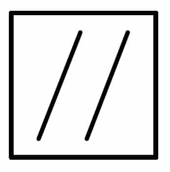
Two straight lines or planes within a specified range. (Datum: required)
- Perpendicularity
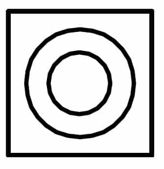
Indicates whether it is at right angles within a specified range with respect to the reference. (Datum: required)
- Angularity
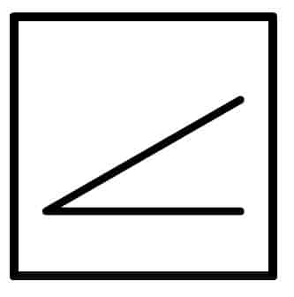
Indicates that the angle is within a specified range with respect to the reference. (Datum: required)
(3) Location
A position tolerance is a geometric tolerance that specifies how it is positioned relative to a datum. Position tolerances are defined to define the placement relationship between the parts so that they themselves are not slightly distorted and prevent them from performing their design function.
- Position
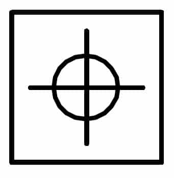
Indicates that the location is within the specified range with respect to the reference. (Datum: required)
- Concentricity
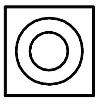
Indicates that two cylindrical axes are coaxial within a specified range. (Datum: required)
- Symmetry
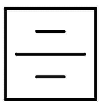
Indicates that the criteria are symmetric within a specified range. (Datum: required)
(4) Run-out
A sway tolerance is a geometric tolerance that specifies acceptable variation. Since the deformation of the outer shape can also be regulated, it is possible to define the shape in more detail than the positional tolerance.
- Circular run-out
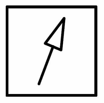
When rotated, some runout within the specified range is achieved. (Datum: required)
- Total run-out
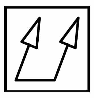
When rotated, the runout of the entire cylindrical surface within a specified range. (Datum: required)
Example Of Entering Geometric Tolerances In Drawings
Now that we have sorted out the types of geometric tolerances, we will explain how to describe them specifically.
Fundamental rules
In geometric tolerances, the rectangular frame is divided into three parts:
- Left border: Enter the geometric tolerance symbol
- Center frame: Tolerance
- Right border: Enter the datum symbol
In the case of shape tolerance, datum is not required, so it is divided into two frames, the left frame and the center frame. For example, if the flatness distortion is 0.1 mm, enter the following:
- Left border: Enter the geometric tolerance of flatness
- Center frame: Enter 0.1
- Right frame: Delete the entire frame (not described)
How To Write If Datums Have Priority
If you need to define more than one datum, separate the right panes according to the number of datums.
For example, suppose there is a specification that a certain part is fixed to the base A and wall B as a reference, and the position of hole C is defined as the degree of position relative to the floor or wall. In geometric tolerances, this situation is first fixed to Datum A (floor) and then to Datum B (wall).
Datums have a higher priority on the left, so if you want to specify two or more datums, put the order of precedence from the left. Therefore, the geometric tolerance is as follows:
- Left border: Enter the geometric tolerance of the positional degree
- Center frame: Enter acceptable numbers
- Right frame: Write A in the leftmost frame, B in the right side of A in the frame
In the previous example, when installing on floor surface A after aligning with wall surface B first, it will be as follows:
- Left border: Enter the geometric tolerance of the positional degree
- Center frame: Enter acceptable numbers
- Right frame: Write B in the leftmost frame, A in the right side of B by separating the frames.
How to write when you want to define using two datums
If you want to determine the position of a part relative to two datums, enter the datum name you want to reference as a reference in one frame as a common datum with a hyphen.
For example, suppose you have multiple cylindrical shapes, such as a shaft, and you want to place multiple parts on the same axis. If you want to arrange part C with a cylindrical part A and part B as references, the following occurs.
- Left border: Enter the geometric tolerance of the positional degree
- Center frame: Enter acceptable numbers
- Right frame: A-B
Geometric tolerances can intuitively define the requirements of a part in a drawing
Since parts have a fixed shape and size, when creating a drawing, it is necessary to have a rule that it is expressed even in a two-dimensional drawing. Geometric tolerance is a necessary condition to express not only the dimensional values and tolerances required for parts, but also the state of parts and parts to each other. In 2D CAD and 3D AD, you can easily draw by selecting a single command and the location where you want to define the shape.