Processes
- Polymer Processing
- Injection Molding Insert Molding Blow Molding Over Molding Metal Injection Molding Thermoforming
- Metal Casting
- Die Casting Castings & Forgings Wax Casting Lost Wax Casting Grey Iron Castings Centrifugal Casting Investment Casting Permanent Mold Sand Casting Shell Mold Casting Aluminum Investment Casting Brass Investment Casting Steel Investment Castings Titanium Investment Casting
- Machining
- Milling Turning EDM machining CNC Engraving Hole-making Tap Size Chart Drill Size Chart 5 axis machining Micro Machining CNC Cutting Metal Processes Ceramic Manufacturing Swiss Precision Machining
Materials
Turning Definition – What is Turning
Turning is a typical form of machining, in which a non-rotary cutting tool moves materials from a rotating workpiece to create turned parts with the desired shape. The turning process is generally carried out on a lathe machine, which allows a number of different turning operations such as straight turning, taper turning, external grooving, etc. In the turning process, the blank (raw material) is fixed and rotated while a single-point cutting tool is traversed along 1, 2, or 3 axes of motion to produce accurate diameters and depths. The turning operation can be either performed on the exterior of the cylinder or inside to manufacture tubular components or other geometries.
Turning is generally used to reduce the diameter of the workpiece to obtain a specific dimension, and then produce cylindrical and axisymmetric turning parts with features like holes, threads, tapers and others. Turning can also be used as the rapid prototyping method and secondary process, and provide tight tolerances and smooth surface finishes.

Turning Equipment – What is a Lathe or Turning Machine & Main Parts of a Lathe Machine
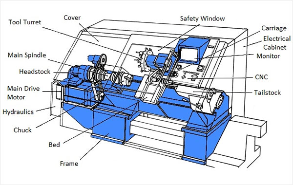
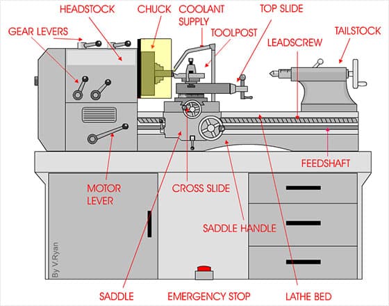
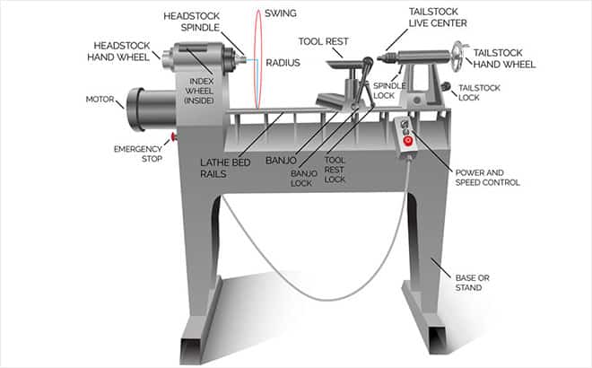
A lathe is a machine tool that rotates a workpiece about an axis to perform various operations including turning, knurling, drilling, facing, etc. The lathe machines can be found in woodturning, metalworking, metal spinning, thermal spraying, and more applications. Similarly, the turning machines come in different sizes and designs, in most cases, horizontal turning machines are used. There are also vertical machines, manual lathes and CNC lathes. No matter which type of turning machine you choose, these main parts of a lathe machine enable the workpiece to be rotated and the cutting tool feed into the piece.
- Bed: a large horizontal structure or beam situated on the ground or table to supports all other parts of the machine.
- Headstock assembly: the front section of the machine, it is the house of the driving mechanism under the electrical mechanism of a lathe machine tool, headstock transmits power from the spindle to the feed rod, lead screw and thread cutting mechanism. It contains spindle speed selectors for controlling gear speed and a driving clutch which is used to engage and disengage the motion at the starting of the lathe. The spindle connected to the headstock possesses live center to which the piece can be attached, there is a hole throughout the spindle for handling a long bar of the block, it supports and rotates the workpiece, which is fixed in a fixture, such as a chuck or a collet.
- Tailstock assembly: the rear section of the machine, made out of cast iron, the tailstock moves on the guideways on the bed surface, and it can be moved forward and backward towards and away from the chuck according to the requirement and job length. The tailstock is used to support the long end of the job for holding and minimizes its vibration and sagging so that the part does not deflect. The dip portion of the tailstock is also called the dead center, which just provides supports and no motion. In the tailstock assembly, we also have the Ram clamp and the handwheel.

- Carriage: located between the headstock and tailstock, used to guide and feed the tool against the job when the machining is done, the carriage holds moves and controls the cutting tools, it gives rigid supports to the tool during operations, it transfers power from feed rod to cutting tool through apron mechanism for longitudinal cross feeding. The carriage consists of five parts: saddle, cross slide, compound rest, dual post and apron.
- Cross slide: attached to the carriage’s top and enables the tool to move closer or farther away from the workpiece, hence altering the depth of cut. The cross slide is powered by a motor or handwheel.
- Compound: attached to the cross slide and acts as a support for the cutting tool. The cutting tool is held in place by a tool post that is permanently attached to the compound. The compound can be rotated to change the cutting tool’s angle relative to the workpiece.
- Turret: can hold multiple tools and rotate the required tools into position to cut the workpiece. The turret also moves along the workpiece, feeding the tool into the material. Although most of the tools are fixed in the turret, live tools can also be used.

Turning Tools – What Types of Cutting Tools Used in CNC Turning?
The cutter for the turning process is usually a sharp single-point cutting tool, which is a piece of metal or a long rectangular tool shank with a sharp insert. These inserts may vary in size and shape but are usually square, triangular, or diamond. Turning tools are inserted into the turret or tool holder and fed into the rotating workpiece to cut the material. These single-point cutting tools come in a variety of shapes, allowing the formation of different features. Some common types of tools are 0-degree lead-angle turning tools, 15-degree lead-angle turning tools, 0-degree square nose tools, 80-degree included angle pointed-nose tools, 60-degree included angle pointed-nose tools, etc. According to the tool material, turning cutting tools can be classified into high-speed steel, carbide, carbon steel, and cobalt high-speed steel.